Between 30/05/18 and 31/08/2018 all activities related to the installation of horizontal patented well screens with high porosity in the middle of the liquefiable layer were carried out by TREVI for both chosen liquefaction mitigation techniques, Horizontal Drains (HD) and Induced Partial Saturation (IPS)
For the HD technique 7 well screens were installed according to two different meshes. The adopted sequence had 3 steps:
- “U” shaped Directional Drilling Ø 75 mm
- Rods’ withdrawal by reaming the hole with Ø 200 swivel device
- Repositioning of reamer and installation of 78 m of welded polyethylene pipes Ø 180 (30 m blind pipes / 18 m well screens / 30 m blind pipes)
A total amount of 576 m of welded polyethylene pipes was set in place with an overall industrial production rate of 5 m/h.
For the IPS technique 4 well screens were installed; the adopted sequence followed two steps:
- “U” shaped Directional Drilling Ø 75 mm
- Rods’ withdrawal by reaming the hole with a Ø 100 swivel device and installation of 78 m of polyethylene pipes Ø 75 (30 m blind pipes / 18 m well screens / 30 m blind pipes)
A total amount of 312 m of welded polyethylene pipes was set in place with an overall industrial production rate of 6 m/h.
The high precision achieved allowed to obtain an average deviation from the theoretical position equal to 0.33%. The chosen operational sequences and methods were aimed at minimizing alteration of the ground natural state, so that reamers with a diameter exceeding well screens’ diameter by about 10% were built up, and a very light (1.25 kg/m³) natural biodegradable polymer slurry was adopted as drilling fluid.
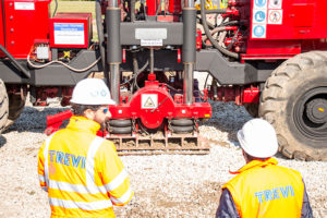
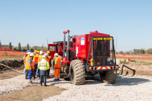
Such an effort required the use of a SOILMEC SM-18 drilling rig, plus ancillary equipment:
- 1 forklift
- 1 backhoe
- 1 Bobcat
The Jobsite Organization Chart has included the on-site presence of:
- 1 foreman
- 1 steering engineer
- 1 drilling operator
- 1 excavator operator
- 1 pump operator
- 1 assistant
Moreover, welders and others employers from the warehouse were involved.
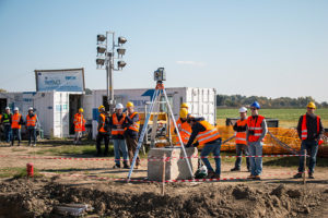
In order to be able to monitor the execution of a full scale earthquake simulation, several devices to measure the built-up of pore water pressure during the dynamic testing have been installed. In detail installation of nos. 9 geophones and nos. 15 pore pressure transducers was carried out.
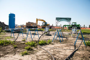
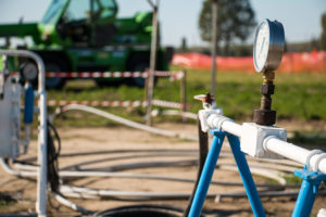
In order to test all the air blowing systems arranged to flush through IPS well screens, a preliminary blowing test was carried out on July 23 and 24. A pressured vessel of 2.000 l at 10 bar was capable of blowing air for 250 l/min along 4 pipes. Each line was connected to a 10 m dissected area of the well screens and, thanks to four manometers and a regulation valve, it was possible to achieve a flow adjustment sensibility equal to 0.01 bar.
In order to check the actual desaturation of the blown-up zone, a total amount of 12 tests was carried out:
- 4 Seismic Tomography P waves
- 2 Seismic Tomography s waves
- 2 Electric Tomographies from surface
- 4 Electric Tomographies from ground level
A Special equipment known as MERTZ M13S/609 S-WAVE servo-hydraulic vibrator is scheduled to arrive on site in the second half of October in order to finalize the test fields by simulating an earthquake: several shakings will be tested in correspondence of both virgin soil and areas consolidated through both chosen liquefaction mitigation techniques.